

My writing of this research article was aided by my library of digital images of Ericson 25s. For quite some time, as I researched one part of the boat and another, or as I shared emails with one person or another, I would encounter pictures of the E25. These I would copy and put into files. As a result of this steady accumulation of images, I was eventually able to recognize many similarities, and also many differences in our boats. I hope to share this library of images with everyone at some point, for it's an incredibly helpful resource in the refitting and maintenance of an Ericson 25.
As I said, I wrote this article for my own research purposes one year ago. Since this article was personal in nature, I freely used pictures of other Ericson 25s to make comparisons. Now that I am publishing this article as a posting on the Ericson 25 blogspot, I must say that if you see a picture of your own boat and you find my use of this picture objectionable, I am happy to remove it. I hope, though, that you will find this article to be educational in nature, and one that is for the benefit of all owners of the Ericson 25.

When I
purchased my E25 in October 2009, I received various old documents original to the
boat, one of which was a large copy (30 in x 30 in) of the original sail plan
by Bruce King, the naval architect who designed most of the boats for Ericson Yachts. In the fall of 2010, I took this sail plan
to an office supply store, and I had them scan it with one of their large machines. Above you see a copy of it in reduced form. It’s very helpful for rigging purposes, since it
includes the specifications. Though it is difficult to see in this copy, all stays
and shrouds are labeled as 5/32 inches. I should note that the rigging in place
when I purchased the boat was also 5/32.The box at the bottom right corner of the sail plan reads as follows:
ERICSON 25
SAIL PLAN DESIGN NO. 1902
SCALE ¾ in = 1 FT. DATE: 2/72
BRUCE P. KING INC.
YACHT DESIGN
2100 WEST COAST HIGHWAY
NEWPORT BEACH, CALIF. 92660
714-616-1716


The first part of this posting will address the standing rigging of the Ericson 25. The standing rigging is, of course, the rigging that supports the mast. Typically, it consists of stainless steel hardware and cable. Standing rigging must be distinguished from running rigging, which is normally associated with the setting and with the trimming, i.e., the adjustment of the sails. Running rigging typically consists of synthetic fiber, i.e. rope. I'll address the running rigging of the E25 in the second half of this posting.
In our examination of the standing rigging of the Ericson 25, we'll begin at the bow and work our way aftward to the stern.
Forestay Chainplate
The forestay begins, understandably enough, at the forestay chainplate at the bow, and from there this piece of rigging extends upward to a stainless steel strap-toggle on the masthead. Below, we see the forestay chainplate (with the flukes of a Danforth anchor hanging down on either side of it) on my boat, Oystercatcher, at the time of her survey in September 2009. Just aft of the chainplate is the stemhead (or stemplate, as some call it) to which is bolted the drum for the roller furler. Note that this is no longer a common location for the roller furler. More on that below.
 |
| Oystercatcher, during her survey, Sept 2009 |

The roller furler on Oystercatcher, the boat that I purchased in October 2009, was manufactured by Schaefer, probably in the 1970s or early 1980s. It is the earliest style of roller furler, from the days when furlers were just beginning to appear on boats. These types of furlers did not utilize rigid metal foils, as do many contemporary furlers. Instead they required the jib (or the genoa) to have a thick wire sewn into its luff. The tack, i.e., the forward corner, of this wire-luff style sail would be secured to the top of the furler drum. The head, i.e., the top corner, of the wire-luff sail would be secured to a swivel, which itself was secured to the jib halyard. With the jib halyard, the crew would haul up the wire-luff sail. Once the halyard was made fast, and once there was thus sufficient tension in the wire-luff, the drum and the swivel could then serve as pivot points for the furling of the sail. Below we see the furler and the jib just aft of the forestay. The furler is bolted to the stemhead.

Here’s a closer view of the furler. The thick stainless steel hardware just above the furler is a large swage-fitted eye. A stainless steel bolt holds the furler to the stemhead. The furling line exits the drum and passes through a teak bulls eye (which stands at the end of an arm that extends from the furler).

The wire, which is sewn into this wire-luff headsail, appears to be 7/16 inch, an incredible thickness, the maximum size sold by many chandleries. I say that it appears to be 7/16 because, it's difficult to get an accurate measurement of it with the sailcloth sewn around it. Nevertheless, I can say without a doubt that it's damn near 1/2 an inch thick.

On account the size of its wire, the wire-luff headsail is an unwieldy creature when not in use. The only way to store the sail neatly is in a coil (a large one at that). The paint can that I placed in the middle of this coil gives you some perspective. This thing would take up much of the V-berth, if you had to store it there. Better to leave it up, but what to do when you want to fly a different headsail, such as a genoa? You have no choice but to drop it, and then hank on the genoa to the forestay.


At the head of the sail is a six foot 5/32 inch wire pendant. It’s to this that the swivel and then the halyard are secured.

Below we see the swivel mechanism. It is connected to the forestay by means of bails. At the bottom of the mechanism is the swivel itself. This is where the six foot pendant is attached. At the top, of course, is where the halyard joins the mechanism. The bails on the mechanism help keep the sail under control when hauling it up and easing it down. The forestay thus serves as a track or guide of sorts.

Schaefer still manufactures the wire-luff style roller furler, albeit in aluminum, not stainless steel. Today they call it the "free-furling system,” presumably because it does not require a metal foil or extrusion, as do most present-day furlers. The Schaefer website indicates that the free-furling system is good for trailerable sailboats because it is easy to set up and take down. It also indicates that this system is good for light-air staysails and gennakers on larger vessels. The 650 model, which is the largest of the three available, is designed for boats in the 25-31 foot range. One advantage of this newer system is that the maximum size of the wire luff is ¼ inch. This smaller size luff wire would eliminate some of the weight aloft. It would also allow you to achieve greater tension with the halyard resulting in a more efficient sail. The Schaefer 650 system sells for a little over $1000, not cheap, but cheaper than the rigid metal foil systems. A disadvantage to this free-furling system, just as is the case with the old version wire-luff system, is that it is not possible to reef the headsail. You’re either all-in or all-out.


From the research I've conducted, I can say that the wire-luff style roller was the first generation of furlers. In other words, the roller-furler as we know it today did not exist. This wire-luff style roller was cutting edge technology in the 1970s. According to the original purchase documents that I received from the previous owner, a wire-luff jib was an original option, one that the first owner paid for (as is evidenced by the check mark on the document below). I'm not sure that my wire-luff headsail is original to the boat, because it is a Hild brand sail. Hild was a sail loft on City Island, New York. The first owner of the boat lived on nearby Long Island. The second owner also lived on Long Island, that is, before he moved to North Carolina in the early 1980s. This was the person from whom I purchased the boat in 2009. If I had to wager a guess, I’d say that the sail now in my possession was purchased in New York sometime prior to the second owner’s move south. It is, though, entirely possible that this Hild brand sail was the original sail for this boat. Ericson Yachts could have had a contract with the Hild sail loft for cutting sails for the E25. There is also the possibility that the dealer in New York, who purchased this E25 in 1975, had the boat fitted with this headsail. I was told by the second owner that the first owner had purchased the boat in 1977, and that it had been in the possession of an Ericson dealer until that time. Whatever the case, may be, this sail had seen plenty of use by the time I took possession of the boat in 2009.

In the picture below, we see the forestay rising up to the masthead. Note carefully that there is only one wire present. In other words, the jib halyard, which should be holding up the wire-luff headsail is missing. This is the way my E25 appeared when I first came to see it at the previous owner’s dock in August 2009. This previous owner did not have the wire-luff jib rigged, but instead had it in storage. He no longer sailed the boat often. Therefore, he wanted to protect the sail as much as possible when not in use.

For the sake of comparison, I include below a picture of the same boat in September 2009. This was when I returned for the survey of Oystercatcher. By this point, the owner had taken the wire-luff jib out of storage and had rigged it on the boat.

Roller Furler (Rigid Metal Foil Design)
Some E25 owners have contemporary rigid-metal-foil style roller furlers. This present-day design usually envelopes the forestay. In other words, there are not two separate pieces of rigging at the bow, as there are in the picture above. Instead, the rigid metal foil surrounds the forestay and uses it as a foundation for the support of the foil. The rigid metal foil needs this stiff foundation because its not very rigid by itself. In fact, it's easy to bend or break the foil without the rigidity of the forestay to support it. For this reason, the rigid-metal-foil style roller furler inhibits easy set-up and removal, so it’s more suited to boats that are not trailer-launched, but instead sit at docks on a seasonal basis. In the picture below, we see a picture of Rob Hessenius' E25. It is difficult to see the details, but this is a Harkin brand roller furler. Rob reports that he has been satisfied with the Harkin and that stepping and unstepping the mast with this rigid-foil furler has not caused him any problems. An assistant must be present to insure that the foil remains rigid while putting the mast up and down. The rigid metal foil consists of tubular sections. If one of these is bent, then it can be replaced.

When it comes to roller furlers, the flexible PVC foil design seems to be the most common type on the Ericson 25 today. This type differs from the rigid foil insofar as the PVC foil is more forgiving of movement, for example, the movement associated with stepping and unstepping the mast, and especially the movement that necessarily occurs when trailering the E25. In the picture below, we see the E25 of a former Ericson owner sittting-up for the winter in Canada. On account of the clear blue sky, we can note many good details. The PVC foil (seen here in bold white) hides the forestay. The small white line that you see behind it is the halyard, used for hauling up the luff of the headsail inside of a small track. We'll address the subject of halyards in the section on running rigging below.

Below, a former owner's Ericson 25 in Missouri, like the one in Canada, has an updated roller furler. We can see clearly here that unlike my early-style wire-luff roller furler, this one is not bolted to the stemhead. Instead, it is integral to the chainplate and the forestay. Unlike the early system, this one, with its more sophisticated drum, allows for the reefing of the headsail. This is a common feature of all present-day roller furlers, whether they are rigid foil or flexible foil, and it is, perhaps, because of this reefing ability, that they are so common.

One of the more common flexible foil furlers that I've seen on Ericson 25s is the CDI brand furler. You can see it in the photo above and also the photo below of a former owner's boat in Texas.


Some E25 owners prefer the traditional headsail set-up, whereby the sail is hanked-on to the forestay with spring-loaded clips called hanks. A benefit of using headsails that are hanked-on is that it provides you with a lot of flexibility in terms of the size of the sail you'd like to fly. For example, if you were flying a large Genoa and decided you needed to switch to small jib on account of an approaching storm, you'd drop the Genoa and haul up the jib. This is the benefit of having hanked-on sails, but this benefit has its limitations. Hanked-on sails, of course, do not self-furl, as do those on a roller-furler. That’s where the crew comes in. Someone must go forward to stow the doused sail and/or hank on the new one. This, of course, can be dangerous, especially when the weather is up. A downhaul can make things easier, and safer, assuming you have the downhaul run aft to the cockpit, and that you have some way of keeping your sail from spilling overboard under the lifelines.
Steve Swann, an E25 owner in Idaho, is a proponent of hanked-on headsails. Here, you can see the hanks, evenly spaced up the forestay, as Steve makes his way through a mountain lake.


Without the self-stowing capabilities that a roller-furler provides, an E25 owner with a hanked-on headsail must do one of two things to stow his sail: either unhank it and stow it below, or bag it. A former E25 owner from Georgia used a bag when docking his boat at Lake Lanier. Note the headsail halyard behind the forestay.

Masthead with Forestay Toggle

In contrast to the forestay, which supports the mast from the bow of the boat, the shrouds, of course, support the mast laterally, from the two sides. There are two types of shrouds on the E25, just as there are two shrouds on many other small to mid-sized boats, the upper shrouds and the lower shrouds. The upper shrouds are the most easily recognizable. They run from the deck all the way up to the mast head.
In the picture below of Oystercatcher, during the time of her survey in September 2009, we see the spreaders extending outward from the mast to port and starboard. The upper shrouds rise up from the chainplates in the deck and pass through the end of the spreaders. From there, they run up to stainless steel tangs near the masthead.

The shrouds, as noted, rise from the chainplates. Below we see two wires attached to a single chainplate. The outer wire is the upper shroud; the inner is the lower shroud (more on that later). Here, we see these shrouds covered by pieces of PVC, a move made by the previous owner to prevent chafing. Often, however, these are left uncovered so as to avoid moisture build-up and thus corrosion. Using black electrical tape to seal off the top of the PVC is definitely not a good idea. This only traps more moisture due to condensation, so said the marine surveyor that I hired.

Chainplates, of course, are of vital importance for the rig. If these fail, due to hidden corrosion beneath the surface of the deck, the entire rig will probably come down. Robert Slocum, an E25 owner in Texas, pulled his chainplates just in time. They were on the verge of failure. There is no way to know whether they are faulty without pulling them, since the most vulnerable area (between the top and bottom holes) is hidden from view within the deck.

Water intrusion from improperly sealed chainplates can also result in rotten bulkheads within the main salon. Quite a few E25 owners (like many other sailboat owners) have had to replace rotten bulkheads on account of the poor maintenance habits of previous owners. Fortunately for me, the surveyor determined that despite the fact that there had been some water intrusion, we caught the problem soon enough. The mahogany bulkhead was still sound.

Considering myself lucky, I pulled the chainplates soon after I made it back home with my newly purchased E25. Though I discovered no cracks, I did find some pitting. This alone was enough for me to condemn them.

Spreaders are integral to the upper shroud system, and must not be ignored in any refitting of an E25. It is not so much the spreaders themselves that deserve attention, but the spreader brackets which are fastened to the mast. Ericson used identical aluminum spreader brackets on the E23, E25, and E27. These brackets, more than any other piece of hardware, appear to be the weakest link in the entire standing rigging system. They have a history of fracturing under stress. In the case of E25 owner Rob Hessenius of Wisconsin, a fractured spreader bracket led to a calamitous dismasting, one that fortunately did not end in serious injury or death, but one that could have, if it the mast had fallen in the right (or we should say wrong) direction. Below is a picture of his E25 soon afterwards. As you can see, the mast itself also fractured in the chain reaction of events that began with the bracket.


In the picture below we see how Rob joined the two pieces of the mast together with a sleeve of sorts and then through bolted on the new Dwyer spreader brackets with compression fittings. These compression fittings (within the mast) are essential for preventing deformation of the mast when tightening the bolt.


Once the upper shrouds have made their way up and over the tips of the spreaders they angle upwards to pieces of stainless steel hardware known as tangs. These tangs are bolted to the mast just beneath the masthead. Here, we see one of the tangs just to the left of the Shakespeare brand VHF antenna. Notice the sturdiness of the stainless steel bolt.

The lower shrouds, true to their name, are lower in height than the upper shrouds. Despite their size, they actually carry more of the load than do the upper shrouds. As Don Casey points out in his helpful tome, This Old Boat, 2nd Edition (2009), the lower shrouds carry 55% of the load, as opposed to the upper shrouds which carry 45%. It’s worth pointing out as well that the 45% load on the upper shrouds is borne not along its entire length, but in the upper portion, between the tip of the spreader and the mast head.
The lower shrouds, as we saw above, are attached to the same chainplates as the upper shrouds. Instead of rising upwards towards the tips of the spreaders, as do the upper shrouds, the lower shrouds rise at an angle toward the spreader brackets on the mast. There, they are joined to stainless steel tangs. These lower shroud tangs are not to be confused with the upper shroud tangs, which are located near the masthead.
In the picture below we see portside upper shroud and lower shroud on my Ericson 25, Oystercatcher as we sailed her through the Pamlico sound on our way to the haulout point, soon after purchase.

In the picture below, you can clearly see both of the lower shroud tangs just beneath the spreaders. If you look near the masthead, you can just barely make out the upper shroud tangs on either side of the mast.

The backstay, like the forestay and shrouds, consists of 5/32 stainless steel wire-rope. Just as is the case with the forestay, the backstay is joined to the masthead by means of a strap-toggle. See the U-shaped piece of stainless steel hardware to the far left of the masthead? That’s the backstay strap-toggle. Although it looks smaller than the forestay strap-toggle on the far right, it’s actually the same size, 2 ¾ inches from the pin to the bend in the strap. Notice that there is also a second, smaller wire in the backstay strap-toggle. That 1/16 inch wire is a topping lift (of sorts). More on that later.

The backstay on the E25 is rigged in what is known as a split-backstay configuration. What this means is that a single backstay descends from the masthead (as described above) until it reaches a junction at a piece of hardware known as a triangle plate. At that point, the backstay splits into two pieces, with one 5/32 inch wire going downwards to the port side of the stern, the other 5/32 inch wire to the starboard side. There, they are joined to chainplates. These two pieces of wire in the split backstay measure 77 inches each. The single backstay with the split backstay configuration is more simple and less cluttered than a double backstay configuration, where two separate backstays descend from the masthead all the way to the chainplates. When there are two separate backstays, chafing of the mainsail is sometimes a problem. The single backstay with the split backstay configuration is also preferable to the single backstay and single chainplate configuration, where the backstay terminates at the center of the stern, and thus puts the entire load in one place. The split backstay configuration, in contrast, splits the load between the two sides of the transom.
In the picture below we see the backstay terminating at the triangle plate, where the split backstay configuration begins. The bungee cord which spans the split backstay was used by the previous owner to keep the tiller out of the way of cockpit activity while docked.

Below we see the port side backstay chainplate. This photo was taken at the end of the transit from the previous owner’s dock to the haul-out point in Oriental, NC on the Pamlico Sound. Note how I made fast the tiller to the port side of the split backstay since I did not have a bungee cord to suspend the tiller as had the previous owner. Notice also the life jackets serving as fenders. When we left his dock the day beforehand, the previous owner decided that the fenders should stay. He had let us spend the night at his dock, and the next morning he let us use his bathroom, so when he said he'd prefer to keep the fenders at his dock, I didn't think it was worth making a big fuss.

Topping
Lift
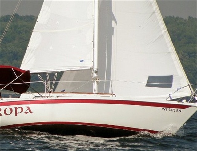
It is
not uncommon for some Ericsons (of various sizes) to be rigged with topping
lifts. The primary function of these topping lifts is to support the weight of
the boom, especially when not under sail. For this reason, most of these
topping lifts are not adjustable. In other words, they are wires of fixed
length that are not capable of being eased or taken-in by means of blocks. In
the picture below of Europa, an E25
in Wisconsin, we see a topping lift at the end of the boom.


While we’re on the subject of backstays, I should also say that some E25 owners make use of split backstay adjusters. These pieces of equipment consist of blocks, which are used to put tension on the backstay. This tension bends the top of the mast slightly backward, thereby affecting the draft of the main. The picture below of Leadbelly is from an advertisement in the 1970s by Ericson Yachts.

Below we see Asylum, the Ericson 25 owned by Californian, John Cyr. John has his split backstay rigged with an adjuster. You will recall that in our above discussion of the wire-luff roller furler, John was mentioned as an E25 owner who uses this type of furler. You will also recall that the wire in the wire luff jibs used in these types of furlers are heavy-duty. Because of the weight of this wire, it can be difficult achieve and maintain tension in the luff of the sail. John says that he counters this by means of the split backstay adjuster. In other words, by pulling the top of the mast aftward, he is able to get good tension in the luff of his headsail.


Running Rigging
Whereas all the information in the first half of this article concerned the standing rigging, in other words, the wire rigging that supports the mast (and, to some degree, the boom), all the information in the second half of this article concerns the running rigging on the Ericson 25. By this, we mean the synthetic, or in some cases a mixture of wire and synthetic, lines used for trimming, i.e., adjusting the sails.
Introductory Terminology
Since the running rigging is more focused on sails than on the mast, we should begin by making a few terms, which concern the rigging of the sails, more clear. Therefore we'll start by addressing the following sail-related terms: sloop-rigged, double head-rig (headsail and staysail), and spinnaker. We'll then end this introductory section with a discussion of the differences between the fractional rig of the Ericson 25 Plus (which went into production in the late 1970s) and the masthead rig of our boat, the Ericson 25 (which preceded the E25 Plus). This introductory material should make the discussion of the running rigging more understandable.
Sloop-Rigged
The Ericson 25 is a sloop-rigged vessel, which means that it flies a single headsail (either a jib or a genoa) forward of the mast, and a mainsail aft.
Double Head Rig Option
A factory option to the standard single headsail rig of the E25 was the double head rig, whereby the vessel could fly a second headsail (staysail). The handwritten Ericson production manual (dating to 1973-74) called for the installation of a stainless steel padeye in the foredeck, 42 inches aft of the bow. This padeye was meant to serve as the anchor point for the second forestay. There were approximately 384 of our boats manufactured from 1973 to 1978. Of the many pictures I have seen of various E25s on he web, I have never seen any examples of double head rigs. Personally, it seems that a double head rig would make the already small foredeck of the boat even smaller and a more difficult space in which to work, especially when anchoring and tending to the headsails. The diagram below from an original informational packet that I received from the previous owner shows the various sails plans available with the double head rig.

Purchasers of new E25s in the 1970s could also opt for spinnaker hardware to be added to their boats during the time of manufacture. The handwritten production manual (dating to 1973-74) provides instructions to workers for the installation of this hardware. Perhaps because of the difficulty involved in setting and striking a spinnaker, and because of the danger of flying a spinnaker during unpredictable conditions, this option appears not to have been widely embraced. There is no discussion of it on the web, and there are no pictures of an E25 with a spinnaker, except those in the promotional literature of Ericson Yachts.

Ericson Yachts ended production of the E25 in 1978 and began production of the E25+ the same year. The E25+ was a different design with a much bigger beam and more head room in the main salon, but with less displacement and ballast. In just three years, 660 of these boats were produced. Sometimes the E25 and the E25+ are confused. Some think that the easiest way to distinguish the two is to look at the portlights, since the E25 has two on each side, whereas the E25+ has three. This is not a fail safe way to distinguish between the two, since some E25 owners have added extra portlights to their boats. According to Seth, the former Customer Service Manager at Ericson Yachts, and now a frequent contributor to the Ericson Forum, the easiest way to distinguish the E25 and the E25+ from afar is the rudder and the rig. E25s have traditional transom-mounted rudders. The plus models, however, have spade rudders beneath the cockpit. In terms of the rig, the E25 is a masthead rig design, which means that its forestay extends all the way from the deck to the masthead. The 25+, on the other hand, is a fractional rig design, meaning that its forestay does not extend all the way to the masthead, but instead terminates several feet below that topmost point. Below we see an E25+ under sail, with her fractional rig clearly visible.

Unless your E25 has the double-head-rig option (discussed above), whereby two headsails can be flown simultaneously, she can only have one headsail up at a time, either a jib or a genoa, of one size or another.
Jib
The jib, being smaller, is by definition no larger than the foretriangle (the space between the mast and the forestay), although sometimes it may be cut larger, say 110%. Some people will refer to these as lappers. I should note that the sail plan information in the original Ericson materials that I received with my boat use the term lapper. At any rate, on account of its relatively small size, the jib (as opposed to the larger genoa) is commonly used when the weather is up, although some may use it as the primary headsail. In the picture from the Ericson promotional literature below we see an E25, under placid conditions, with what appears to be a lapper jib.


The genoa, in contrast to the jib, is often cut to 130% to 150%, or even larger. This means that it extends 30-50% aft of the mast. Some E25 owners use a genoa as their primary headsail. Both of the boats below appear to have genoas on roller furlers.


Jib Halyard
As I noted in the discussion above concerning the wire-luff roller furler, the 7/16 inch wire within the luff is swaged at its topmost end with a stainless fitting. To the eye of this swage is connected a 5/32 inch wire pendant, 6 feet in length.

The 6 foot wire-rope pendant is itself attached to the roller furler swivel mechanism (discussed above), which is, in turn, attached to the jib halyard. This halyard consists of 30 feet of wire-rope, to which is spliced a braided line. In the pictures below, we see that the wire-luff jib itself on my boat terminates around the bottom of the topmost mast step rung. This rung is 8.5 feet from the top of the mast head. Therefore, we can say that the 6 foot wire-rope pendant terminates about 2.5 feet from the masthead. This is good, for it allows plenty of space for the wire-rope halyard to make its way up over the sheave within the masthead itself. In the picture to the far right below, you can see the point at which the pendant, the swivel, and the snap shackle of the halyard join each other, about 2.5 feet from the masthead.


Reeving
of the Jib Halyard Through Masthead Sheaves
There seems to be a mess of wires at the masthead, but everything here is quite orderly. To the far right is the forestay, attached to its strap-toggle. Between the forestay and the mast there are two wires. One is the jib halyard. The other is the main halyard. The jib halyard is reeved fore to aft. In other words, when you haul away on the jib halyard to set the jib, the halyard travels up the forward end of the mast, over the sheaves, and down the aft end of the mast. The main halyard travels in the opposite direction.

There are four total masthead sheaves, all V-grooved and sized for 5/32 inch wire. From this picture’s perspective, the jib halyard is reeved along the bottom row, and the main halyard along the top. If this mast were stepped and we were looking down on this masthead from the sky, the jib halyard would be on the portside, the main halyard starboard.

The winch for the jib halyard is located on the port side of the mast. This makes sense, because the jib halyard is reeved through the portside sheaves on the masthead.

Although many E25s, including my own, have the Jib Halyard Winch on the port side of the mast, some have them on the starboard side. For example, in this picture from the Ericson promotional literature of the 1970s, there is what appears to be a bronze winch on the starboard side.

Wire-To-Rope Halyards are halyards that have wire on one end and rope on the other. The wire end is the one close to the sail, the rope end the one close to the winch. All Ericson 25s (as well as numerous other types of Ericsons) were originally rigged with wire-to-rope halyards. Many owners continue to use these types of halyards. In their day, wire-to-rope halyards were a means of achieving greater tension and thus more efficient sails than all-rope halyards.
All-Rope Halyard, Defined
Today, with the advent of high-tech, low-stretch synthetic lines, some owners have re-rigged their boats with all-rope halyards. This helps to reduce weight aloft, and it reduces wear and tear on the mast due to the chafing action of the wire halyards. You might find re-rigging your Ericson 25 with all-rope halyards to be beneficial. Keep in mind, though, that this will require a replacement of the masthead sheaves. More on that below.
Wire-to-Rope Halyard on Boat I Purchased
The wire-to-rope jib halyard on the boat I purchased was either sized incorrectly or had been stretched beyond a serviceable condition by the previous owner. Notice in the picture below that some of the wire portion of the halyard is wrapped around the winch. The thimble to which the rope portion of the halyard was spliced is clearly visible on the drum of the winch. You can't see it in this picture, but the drum is scored from repeated contact with the wire and thimble. This should not have happened. The previous owner should have shortened the wire portion of the halyard or shortened the six foot pendant between the halyard and the jib. I took this picture on the Pamlico Sound during the transit from the previous owner’s dock to the boatyard in Oriental. Note that even with the wire and thimble wrapped around the winch there is still not enough tension in the luff of the wire-luff headsail.


This E25 on Lake Michigan in 2004 displays the sheeting commonly seen on boats of this kind. The sheet on this genoa runs from the clew of the sail down to a block on the sheet rail, and from there it runs up to the winch on the cockpit coaming.


The main halyard on my E25, like most E25s, is rigged on the starboard side, opposite the jib halyard (and the jib halyard winch) on the port side. The main halyard is made fast to a cleat. On both sides of the mast we see the coiled portions of the halyards hanging from cleats.


While we’re on the subject of the main halyard, we might as well talk about the boom downhaul on the E25. The main halyard, of course, supplies tension to the luff of the sail aloft. The boom downhaul, on the other hand, supplies tension to the luff in the opposite direction. On some types of boats, especially racing boats, this downward tension is supplied by a Cunningham, a line that is incorporated into the mainsail itself. On the E25, however, a boom downhaul is the standard way of achieving this tension. In the picture below, we clearly see the boom downhaul. It begins at an eyelet in the gooseneck and runs downward to a cleat near the bottom of the mast.

The vang is yet another means of achieving tension in the mainsail. Typically, a vang is a block and tackle system that extends at an angle from the base of the mast to the boom. The vang serves to pull the boom downward and thus counter the upward pull exerted by the mainsail. I've seen quite a few E25s that are rigged with vangs, including the boats in the promotional literature by Ericson Yachts. The picture below is the best photo I've found. Don't confuse the vang, which angles upward from the base of the mast to the boom, with the block and tackle system of the main sheet in the left of the picture. We'll look at the main sheet in the information below.

The original traveler system for the Ericson 25 was designed for mid-boom sheeting of the mainsail. Accordingly, the traveler system includes not just a track and a car, but also a bridge that spans the companionway. The bridge is of heavy duty construction consisting of aluminum, ¼ inch in thickness. The legs of the bridge as well as the track and the car are stainless steel. The entire system weighs 10.5 lbs. The manufacturer was a company whose logo is stamped on the traveler. The logo depicts an anchor with the letters RC on either side of the shaft. This company is apparently no longer in business, since there is no information whatsoever available about it on the web.

Quite a few E25 owners have expressed displeasure with the original traveler system. Specifically, there are complaints about the difficulty in adjusting the car, especially when under sail. There are spring-loaded pins on either side of the car that must be pulled up and shifted in one direction or another. Holes within the track provide stopping points for the pins.
On the E25 below, we see an OEM traveler that has been modified. On either end of the car, there are blocks, and on either end of the track, there are cleats. These modifications would appear to provide only marginal improvement on the original system, since adjustment of the car would require two different adjustments on the cleats, both of which would require a crew member to brace himself in the companionway and lean forward to reach the cleats themselves.


The OEM mainsheet blocks for the E25 were manufactured by Seaway, a company in Southern California that was in business from the early 1970s to the early 1990s.


Before we close this survey of the rigging of the Ericson 25, we should mention flag halyards and ensigns, not necessary parts of the rig, but customary ones.
Flag halyards are lines that pass through blocks on the spreaders. Some boats have one flag halyard on each spreader, some have just one total flag halyard, some have none at all.
In the picture below, a former E25 owner from Illinois flies a Norwegian flag from his starboard spreader. When sailing in foreign waters, this is the position of honor reserved for the courtesy flag, i.e., the flag of the country in which you are sailing. I doubt that this owner was sailing his E25 in Norway at this time. In coastal waters, this starboard halyard is often used for the flying of a courtesy flag for the state through whose waters you are passing. In home waters, it's often the position for one's own state flag.


At last we have come to the end of this tour through the many terms associated with the rigging of the Ericson 25. I hope that this article will benefit every owner in his quest to make his boat as shipshape and seaworthy as possible.
My rig has the factory staysail and spinnaker setup. Would you like pics?
ReplyDeleteSteve Hemphill
"Old Navy" #67
Steve,
DeleteYes, I'd really like to see some pictures of your set-up. Thanks for getting in touch.
Roscoe
Hi,
DeleteI have a 73 E25 and have enjoyed your posts very much. Did you ever get the pics of the staysail setup from Steve?
Hello John,
DeleteThanks for the compliment. Yes I did get those pics. I removed that article when I changed the focus of this webpage from the Ericson 25 in general to my own E25 - Oystercatcher. I'll repost it, since you asked.
Regards,
Roscoe
Thank you very much. I enjoyed it and found it informative.
DeleteThank you very much. I enjoyed it and found it informative.
DeleteMany hearty thanks for all the time you invested in this well presented article, it is quite interesting and very nicely done.
DeleteThanks, Donald.
DeleteThanks for the compliment John.
ReplyDeleteWell done. I have indtallrd a Schafer furler on thr E25 .Should there be mast prebend in the headstay tuning. In using rhe Loose guage . What is the prescribrd poundage on the upper and lower shrouds?
ReplyDeleteI don't use a gauge. I simply allow for 1 inch of movement in the shrouds with my two finger tips pulling on them.
DeleteThis comment has been removed by the author.
ReplyDeleteFYI you have your forestay toggle in the wrong location at the mast head. The pin you have it on (the top most forward one) is where you would attach the spinnaker halyard block. Thats a smaller pin than the one that should hold the forestay.
ReplyDeleteYes, you're right, Gabriel. When I rerigged her back during my lengthy refitting (2012-15), I riggeed her as I had found her. During my lengthy yard period of 2019-20, which I recently wrote about, I almost considered moving the forestay toggle so as to accommodate a spinnaker halyard. I just ran out of time. It's on the to do list for the future.
ReplyDeleteThanks,
Roscoe