|
| Planing Down Rough-Sawn Mahogany to Construct the New Hatch |
|
Introduction
Whoever says that building a new companionway hatch is
easy, is one of two things: either a master craftsman or a bald-faced liar. Even if he happens to be a master craftsman, he must, nevertheless, set aside a considerable about of time and money to build a companionway hatch. If he is not well-skilled with the saw, and if he's not in possession of a good number of shop tools, then he should plan on setting aside a little more time and money to account for the difficulty of this project and any errors he might make along the way. One thing, however is probable: his task will be made a good bit easier on account of this article and the many pictures I have provided within it that document my own companionway hatch project.
I don't claim to have discovered the best way or the easiest way to construct a hatch, but at least, after some amount of trial-and-error, I figured out
one way to do it. I was aided to some degree by various pictures I found here and there on the Internet that gave me some vision of how to proceed. I was also fortunate enough to have the original hatch in my possession. All in all, though, I found that, at almost every step of the way, I was forced to think and rethink where I had come from and where I was going, simply because there was no book or Internet resource that provided enough of the information I needed to carry this project from start to finish. If this article helps you approach the task of building a new companionway hatch as less of a head-scratching puzzle to be solved and more of a project to be enjoyed, then it will have served its purpose.
Part I: Mold, Shell, and Frame
The first part of this four-part article concerns the construction of the mold, the shell, and the frame. To put it in the most simple terms possible, the mold is a temporary and expendable creation that is used merely as a means of shaping the curved shell of the new companionway hatch. If we were to conceive of this hatch in home-construction terms, we might say that the curved shell serves the function of the roof. The frame, on the other hand, which we address towards the end of Part I, serves more as the foundation upon the whole house is built. Why I built the roof first, and the foundation second will only become clear as you read further.
 |
| Old Hatch as it appeared during my first visit to Oystercatcher, August 2009 |
Section 1: Deconstructing the Old Hatch
The construction of the mold was made much easier by the deconstruction of the old hatch, the old shell of which served as a helpful pattern for the establishment of the curvature proper for the mold, and thus the curvature proper for the new shell for the new companionway hatch that was to be constructed. While this might sound like a perfectly rational way to approach the beginning of this lengthy project, it was more a product of happenstance - an afterthought that came to me only after I had come to the realization that my plan to shore up and repair the original, badly-weathered hatch was a misguided waste of time and energy.
I won't go into the details of the bad condition of the original hatch or the former owner's half-hearted attempts to pretty it up by slapping a couple coats of varnish on it. I've discussed this at length in the earlier article, "Companionway Hatch, Original," if you're interested.
 |
| Original Companionway Hatch as it appeared after former owner applied a little varnish, Sept 2009 |
Yes, my original plan, after I purchased the boat in North Carolina and got her back home to Charleston was to try to strengthen the old hatch and restore it to a good, workable condition. A neighbor with trans-Atlantic sailing experience said it was at least worth a try.
It wasn't difficult to remove the old hatch from the boat, because of the rotten state of the wood in the area of the slides or runners. All I had to do was jiggle the hatch back and forth a few times and then lift it from the stainless steel slides. This all happened so quickly and with such little effort that I forgot to take a picture.
Once I had the hatch off the boat and sitting on some sawhorses inside my work room, I began a systematic examination, in order to determine what work needed to be done. I started by removing the aluminum angle pieces that the former owner had installed, at some point to, strengthen the structure.
It soon became clear that the teak, which had lain hidden beneath the aluminum angle pieces for a long time, was in wretched condition. Even though it was teak - the most rot-resistant wood known to man - it was showing many signs of decay.
The starboard side of the teak frame of the companionway hatch was so rotten, that it simply fell off the hatch when I unscrewed the aluminum angle piece. This was the only thing that had been holding it in place.
The first two slats of teak on the starboard side slid off of the fiberglass shell with little effort on my part. To me, it appeared that years before this time the polyester resin, which had been used to adhere these slats to the shell, had given up its grip. The dark splotches on the fiberglass shell appeared to have resulted from the accumulation of mold and mildew in the cracks and crevices.
Before I moved on to the next side of the hatch, I flipped the hatch over and took a picture of its underside. Here, if you look closely, you can see some distortions in the fiberglass shell. If you've read my earlier posting on the original companionway hatch, you'll recall that on the transit to Oriental, North Carolina, soon after my purchase of the boat, I placed one foot atop the hatch while stowing the main sail, and at that time heard a crack and a crunch beneath my foot. Here, then, are the results of that crunch.
Next, I turned the hatch back over to its top and began to focus on the portside aluminum angle pieces.
My initial impression of the condition of the teak that I found beneath the aluminum was not very promising.
Just as was the case with the starboard side, the first two slats on the portside easily broke away from the rest of the structure. Years of water intrusion had taken their toll on the polyester resin of the shell.
Here's a good view of the rot in the area of the frame-to-shell joint on the portside, aft.
The portside forward joint was almost as bad. Note well the screws, here and there. The former owner had probably tried to reinforce the hatch in this way before resorting to the aluminum angle pieces. These screws looked like they had been in place for a long time, but they didn't appear to me to have been original.
While we're at it, why don't we take a look at the joint on the forward end of the starboard side. The screws, as you see, were offering nothing in the way of strength and support. The shell, I should point out, did not contain any wood. It consisted entirely of resin-impregnated cloth, and it was, at most, only about 1/4 inch thick. This is one reason why I believe that the screws were not original to the structure. There just wasn't enough of an edge on the shell for them to grab and hold it in any effective way.
The joint on the aft end of the starboard side was the most pathetic of them all.
During this examination of the original hatch, I also took a few pictures of the joints of the frame. I believe that the single bronze screws in each of the four corners of the frame were the only screws original to the structure.
Here, as in the picture above, you see that it was not just the sides of the frame that were beyond repair, but also the forward and aft pieces. Given everything I had seen up to this point, there was no doubt that this companionway hatch was beyond repair.
One more corner shot before we move on to other things . . .
Here's a view from above, at this point in the deconstruction process. I figured that the most I could do at this point in the game would be to extract as many pieces as possible that might be useful for the construction of a new hatch. My plan was to focus on the teak planks. I thought it would be nice to preserve the originals, and I figured it would save me a lot of money, especially given the price of teak these days. To begin the extraction process, I knew that I first needed to remove the teak pull-piece that arced over the top of the planks. You can see this pull-piece below, on the right.

Unfortunately, the pull-piece proved to be much more firmly secured than any of the other pieces of wood I had encountered up to this point. At the Ericson yard in 1975 they had secured the pull-piece with lots of screws on the underside of the hatch. I had to hunt around for the heads of these screws with a drill, and a Roto-Zip. I eventually dug out holes (around these screws) which were large enough for me to extract the pull-piece from the top side of the hatch (with the mangled screws still firmly in place within it).
The picture below should give you some idea of how much of a pain it was to dig out these holes.
If you've ever used a Roto-Zip, you know that it can be a mean little sucker. On this job, however, even with the proper bit, this tool was up against a formidable opponent - one that did not go down without a fight.
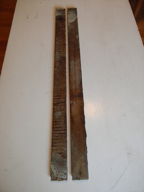
Once I had finally removed the pull-piece, I turned my attention to the the removal of the teak planks from the fiberglass shell. The first couple of planks were not very difficult to remove, but those that followed were next to impossible to extract. After a struggle, I was able to get a few of them off. When I turned them over, to inspect their underside, I discovered the reason why they had had such a tenacious hold on the fiberglass shell - they had been given cross-cut kerfs prior to their installation. Below, on the left,we see one of the slats with kerfs. On the right, is one without.
The close-up shot below should help to illustrate my point. I should point out that the yellowish gunk on the ends of the plank is the result of the spray-foam that the former owner squirted into some of the crevices of the hatch in an effort to seal it up.

If you take a close look at the edge of the kerfed slat below, you can see that the kerfs are only about 1/16 inch below the finished surface of the teak. The hump of sorts near the end of the plank is the place where the curved pull-piece had been attached. Why the hump, you might ask? It was not original to the hatch. It was merely the high ground, so the speak, after the rest of the teak around it had been eroded - by repeated sanding and refinishing over the years. In other words, the entire plank had originally been as thick as it was in the humped area - about 3/8 inch. Now, most of the plank was only about 3/16 inch. If all of the planks lacked kerfs and were about 3/16, I might have tried to reuse them on the new hatch. Since, however, the kerfed planks only had about 1/16 inch of finished teak left on their surface, and since I would need to sand and refinish these slats if I reused them, I decided, with some dismay, that my plan to reuse these teak planks on the new hatch would have to be abandoned.

The picture below of me flexing one of these kerfed planks should give you a good sense of just how thin the finished surface of the teak was on the original hatch.
Here you can see just how close to finished surface of the teak the kerfs extended. You can also see the crummy quick-fix that the former owner attempted with the spray foam. If you've ever used Great-Stuff spray foam to seal a window or door, you know how much this material expands. I would think that it made the problem worse, rather than better. Cheap fix. Cheap results.
A couple of the kerfed planks clung so fiercely to the fiberglass shell that they snapped as I tried to extract them, despite my slow and deliberate approach to their removal. Enough was enough, and with that I began to focus on how make use of the shell of this old hatch as a pattern for the construction of a new one.
Section 2: Building the Mold and Laminating the Shell
I did quite a bit of research, both in books and on the Internet, before I decided to approach the initial stages of the creation of a new companionway hatch in the way that I approached it - through the construction of a mold. I was aided in my research by the work of Doug, an Ericson 27 owner in Oregon with whom I conversed on numerous occasions before and after that time. If you'd like to check out Doug's work for your self, visit his page:
http://plasticclassicforum.com/forum/viewtopic.php?f=37&t=4431
The purpose of the mold is to establish a surface (with the proper curvature) to which pieces of plywood can be clamped and thus shaped to form the shell for the new companionway hatch. Before I deconstructed the original hatch, I took many measurements to ensure that I had the numbers I needed in the event that the construction of a new hatch was necessary. With these numbers, and with the original shell as a pattern, I constructed a mold that was several inches longer and wider than the existing shell (so I could build the new shell slightly larger and then cut it down to the exact size when necessary).
For some reason, I didn't take any pictures while I was in the process of constructing the mold. I do remember, though, that I used 1x6 material for the
rafters, so to speak, if we are to conceive of this as a roof of sorts. Do you see the curved piece of material on the front of the mold? I cut all of the rafters according to this curved pattern. On the right hand side of the mold you'll notice a row of eight, evenly-spaced screws running forward to aft. These indicate the position of the eight rafters beneath the plywood cover.
It's a little easier to see the row of eight screws in the picture below.
The beauty of using a healthy number of 1x6s to construct the mold is that the left-over pieces can then be used as assistants of sorts to the clamps when it comes time to laminate the plywood pieces for the shell. The proper term for a piece of wood that is used in this fashion is a
caul.
Here's a closer shot of the eight cauls resting upon the mold, ready for action.

When the time came to laminate the two pieces of plywood together to make the shell, I didn't take any pictures of the actual laminating process, because I was too wrapped up in the prep work and in the mixing and spreading of the epoxy. For the record, though, here's how I did it. First, I bought a sheet of 1/8 inch luan from Lowe's. Luan is another name for Philippine mahogany. Despite the fact that it's a member of the mahogany family, it's not expensive like other varieties. Nevertheless, like other mahoganies, it is rot-resistant to some degree. It's for this reason that it's widely used as a sub-floor sheath when laying vinyl floors in kitchens. This is also why it's not hard to find at Lowe's. At any rate, I cut two pieces of the luan to size. Next, I stapled two pieces of plastic to the mold so that any excess epoxy would not adhere to the mold. Then, with as many clamps as I could muster from my own work room and my neighbor's, I got the epoxy ready to mix.

As you can tell from the pictures, I used MAS Epoxy, specifically the F.L.A.G (filleting, laminating, and gluing) version, which is thicker than usual. Using the Medium Hardener and many scoops of wood flour and colloidal silica for flexibility and strength, I mixed it all up, poured it out, and spread it with a notched, plastic spreader. This technique, which leaves ridges and swirls of thickened epoxy all over the surface is not unlike that used in the spreading of mortar just prior to the laying of ceramic tiles. Speaking of tiles, you notice, of course, that I used eight boxes of tiles on the center area of the cauls to ensure that there was plenty of pressure in this area where clamps could not be applied.
Some might find fault with me and point out that with all that weight, I probably applied too much pressure, thereby
starving the joint, as some people say. I will hasten, to point out, however, that during this laminating process I was guided by an acquaintance with professional experience in cold-molded boat construction. To his mind, we achieved just the right amount of
squeeze, as it's called, from the edges of the plywood.
Since I was busy with other projects in and around the house, I decided to let this entire set-up just sit on my porch like this for about three months. The Admiral was none too pleased, but at least I was keeping her happy by working on other things that were of immediate interest to her. When I finally took everything off the porch, I was happy to see that the plywood laminates, in other words, the new plywood shell, did not spring back at all. The months of pressure and clamping had convinced the fibers of this wood that there was a new boss in town. They conformed to the new order of things and never thought about returning to the status quo.
Section 3: Making the Mock-Up Frame
The next step I made in the construction of a new companionway hatch was to build a mock-up frame that would serve as a pattern for the real frame. Given the cost of exotic woods, I thought this would be a wise course of action, and as it turned out, it was. If I had not gone through the trial-and-error process in making the mock-up, I certainly would have had to go through it with the expensive wood, and that would not have been good.
Once again, I'll say that I was fortunate to have in my possession the old and worn pieces of the original hatch. Without them, I would have been lost.
One of the problems that I ran into during the tracing process was that the ends of the frame pieces were often cracked, missing, or disintegrated.
For this reason, I just had to make my best guess with the pencil, and then jump in there with the saw. After I cut the piece you see below, I thought it would be helpful to me (and to anyone else who might have to do this in the future) to take measurements of this piece. I did take the time to make these measurements, but, in the end, I don't think they're really very helpful. Why? Because, I ended up cutting and sanding so much on this piece (and on the real piece that followed), that it would be misleading for me to present these measurements as precise guidelines. More helpful, I believe, are the pictures that I provide here. With these pictures, and your own precise measurements of your own companionway, you can deduce the correct numbers for your boat.

Let's take the picture below as an example. Even though I had used the original piece as a pattern for this mock-up piece, I still had to make quite a few trips back and forth from the boat to the saw to get the plywood mock-up piece to fit correctly. All boats, even those from the same mold, such as the Ericson 25 will vary slightly. Even parts of the same boat will vary slightly. My own companionway, for example, was not perfectly symmetrical. There were slight variations between port and starboard. In short, a companionway hatch, at least from my experience, is a custom job that requires custom cuts at many steps along the way.
Satisfied with the aft end of the mock-up, at least for the time being, I moved on to the forward piece.
Then I turned my attention to the side pieces of the mock-up frame. I used the table saw to cut rabbets along the length of the pieces.
One of the more challenging tasks in the construction of the mock-up was figuring out the measurements for joining the pieces. The rabbet had to be deep enough to accommodate the stainless steel runner, but it couldn't be too deep. Balance was the key for both pieces. There needed to be just enough room for the hatch to slide, but not enough room to allow it fly off of the track. Once again I had to make many trips from the boat to the saw to get both these pieces to fit just right.
There was the additional challenge of cutting a rabbet on the interior of the frame - a rabbet that would accommodate the plywood shell. Notice the straight bit on the router. I had to free-hand this cut along a pencil-line I had made in imitation of the curvature of the top of the piece. The cylindrical rabbeting bit that you see in the background was not sufficient for depth and the style of this cut.
Another shot of the rabbeting process.
You can tell from the many marks on the piece below that I had to make many adjustments before I finally arrived at a mock-up frame that fit together (and fit within the parameters of the companionway and the runners) in an appropriate manner.
When I finally assembled the four pieces of the mock-up frame, it seemed that I was making good progress, at least in this early stage of the game.
Section 4: Making the Mahogany Frame Pieces
Sufficiently pleased with the mock-up, I decided it was time to transition to the construction of the real companionway hatch frame. This transition demanded that I select a good wood, suitable for this project. As a first step, I consulted that acquaintance of mine who'd helped me with the lamination of the shell. As a professional boat-builder who specialized in the cold-molded process of construction, he was accustomed to using many varieties of woods. His first suggestion was that I use teak. His second suggestion was that I use sapele (pronounced sa-PEE-lee), an African wood in the mahogany family. He said that this was a commonly used wood in the boatyard with which he was affiliated in Charleston.
With this boat-builder's advice in mind, I visited a local lumber yard, Southern Lumber, to see what I could find in the way of teak and sapele. I discovered that they had little in the way of teak, and what they did have was expensive, although priced competitively with the teak that was available from online distributors. When it came to sapele, however, I discovered that their supply was abundant. Moreover, I learned that, although not cheap, it was some 75% less expensive, per board-foot, than the exorbitantly priced teak.
Before I ever made the trip to Southern Lumber, I did a little research on this wood called
sapele, which I (and others) often simply call
mahogany. The scientific name for the mahogany family, a family of flowering plants an trees found in many of the tropical regions of the world, is Meliaceae. Within this family there are three different species that are commonly harvested, sold, and used as
mahogany for wood-working purposes. Swietenia macrophylla, often called Honduran mahogany, is native to Central and South America.
 |
| Honduran Mahogany |
Honduran mahogany has been harvested for centuries and for this reason it is no longer commonly available. Where it is available, it is expensive. I should note that Southern Lumber indicated to me that they had stopped stocking Honduran mahogany at some point in the recent past. The other two species of mahogany are native to Africa. One is khaya (Khaya ivorensis or Khaya senegalensis), the other, sapele (Entrandrophyragma cylindricum).
 |
| Khaya, African Mahogany |
I discovered during my research that people often confuse these two species, since they are both from Africa and they are both called mahogany. Many people will thus refer to either of these species as African mahogany. Often, however, online retailers make a distinction, referring to khaya as African mahogany and sapele as sapele. Certainly purists and professional wood-workers who specialize in exotic woods can tell the differences between Honduran mahogany, khaya, and sapele, just as oenophiles with sensitive palates can detect the subtle difference between the grapes grown in one region of France and another, but to me all three of these species of mahogany - Honduran mahogany, kaya, and sapele - are very similar in appearance and beauty. For this reason, from this point forward, I will refer to sapele the way I usually refer to it when conversing with others - simply, as
mahogany.
 |
| Sapele, African Mahogany |
As is customary, exotic woods at Southern Lumber, are sold by the board-foot in a rough-sawn condition. This means that you have to take your wood back to your shop or your home and mill it down to a workable condition by yourself. Usually the wood is in a good enough condition that you can achieve this workable condition by running it through a bench planer several times and then running it through a table saw to clean-up and square-up the sides. Sometimes, in my experience, a hand-planer on the sides is sufficient.
I selected several rough-sawn boards at Southern Lumber of various thicknesses for companionway hatch project and for other projects (that I will document in other articles). For the sake of example, let us take a look at several pictures that demonstrate how I converted one of these pieces of rough-sawn wood into useable wood.
The piece I have chosen is 8/4 inches its rough-sawn state. I selected this 8/4 inch (2 inch) sized material to make the mahogany slats for the hatch. Below you see me preparing to push this large piece of material through the planer.
I wanted to remove as little of the material as possible. Therefore, I set the planer to where the blades just barely made contact with the wood. The dark, rough-sawn splotches in the picture below indicate shallow areas in the wood. I would need to keep lowering the blades and passing the material through the planer until all these splotches disappeared.
Here's a close-up shot of the rough areas of the material.
An even closer view reveals the rough marks from the original milling process in Africa.
After another pass or two through the planer, the wood was starting to look pretty clean.
Eventually, I was satisfied enough to stop the planing work. A sander could do the rest.
I then turned the piece on its side and prepared to hit it with the Bosch hand planer.
In this close-up shot you can see the saw marks from the mill in Africa.
After a pass or two with the hand planer the side of the piece looked good enough.
The quality of this picture leaves something to be desired, but it still illustrates well-enough the smooth surface that was achieved with the hand planer.
The mahogany that I selected for the companionway hatch frame was 6/4 inches (1.5 inches) in its rough-sawn state. By the time I finished planing it, I had a piece of material that was 1.25 inches. Although this was 1/2 inch thicker than the teak on the existing frame, I figured that it was a good idea to start with plenty of material in the event that I needed to plan it down to make it all fit together and fit on the companionway properly.
I decided to start with the side pieces of the frame, since these were just straight pieces with right angles. Why not get accustomed to working with the mahogany by tackling the pieces that were the easier ones to fashion? That was my thinking. Despite what I had read online about sapele mahogany being a wood that was relatively easy to work, I found that it was strong, dense wood that required sharp tools. Matter of fact, it only took one cut on the original 6/4 board for me to decide that I had better stop what I was doing and go buy a brand new saw blade for this project.
After I had cut the first side piece, the next task was to use the table saw to cut the rabbet for the stainless steel companionway hatch slide.
It certainly helped to have that piece from the mock-up frame. Constructing that mock-up ended up saving me a lot of time and money when it came time to make the real thing.
In a short time I had produced both of the side pieces for the frame.
Putting away the side pieces for the time being, I focused on cutting a separate piece of mahogany that I had purchased at Southern Lumber. Although it is difficult to see in the picture below, this piece of material is not 6/4 inches (1.5 in.), as was the first one, but 8/4 inches (2 in.) in thickness.
Given the price of the mahogany, I did everything I could to extract as much as I could out of every inch of every board.
The Makita miter saw delivered the straight and clean cuts I needed, even when it was up against this mahogany that was 2 inches thick.
Once I had the smallest piece that I needed from that 2 inch thick board, I started ripping off 3/8 inch pieces from it, one rip at a time. These 3/8 inch pieces would eventually serve as the planks for the plywood shell.
Throughout this project and the many other mahogany projects that would follow, I would grow to love the smell of this wood. It has a rich, sweet smell unlike any other.
As the material became smaller and smaller in size, I had to rely on the blue push-block on the right to keep my fingers safely away from the blade. I have a healthy fear of this tool, and as long as I maintain this fear, I think (hope) all my extremities will remain intact.
The most precarious cut of them all. Nevertheless, it was something I thought I needed to do it. This large piece of wood produced just enough 3/8 inch planks to leave me with two spares.
Next, I focused on cutting the fore and aft pieces of the hatch frame from a spare piece of the 8/4 inch material that was left over from the cutting of the planks.
Again, I made a point of cutting the mahogany to get the most out of each piece.
Since this was 8/4 material, I needed to take it down at to 6/4 or 5/4 so that it would be of a thickness that was similar to the side pieces that were 5/4 inches. The planer, which I had borrowed from a buddy, was having some problems on this day, so I tackled this job with a Bosch hand planer.
This was not an ideal situation. It took many passes to begin to make a dent in this dense material.
It was also not always easy to keep the material a consistent thickness, since the the planer was much smaller than the surface I was planing. Regardless of these obstacles, I eventually got the material down to a workable size.
That hand-planing job might have seemed hard, but it wasn't really as hard as the next task that awaited me - cutting the curved frame piece from this thick and often unforgiving wood.
If you look closely at the picture below, you'll see that I made two different pencil marks on the mahogany as I traced the outline of the mock-up piece. I made a second pencil line, beyond the line I traced around the mock-up piece, because I thought it would be a good idea to have more material to work with in this area of the frame. At it turned out, this was a wise decision. I needed this extra material. This only proves the point I was trying to make earlier in this posting - that it would be misleading for me to provide anyone with precise measurements for this project. This is the sort of thing you just have to feel out as you go along.

Once I was satisfied with the sketch I had made on the mahogany, I decided it would be smart to back up my work by following that oft-uttered adage, "measure twice, cut once." To double-check myself, I thought it best to pull out my Montgomery level. If you've never seen one before, I can say that they are very useful in dealing with the many curves and angles on a boat. With a nod to my fair city of Charleston, I should note that the guy who invented this tool is a resident of this locale.
It's hard to tell in this picture, but the angle of this slide on the starboard side is about 8 degrees.
The angle of the slide on the portside, on the other hand, is about 10 degrees. This is one example of how the companionway differs on one side as compared to the other.
It seemed to me that the slide on the starboard side was slightly bent, so I thought it would be good to use 10 degrees at the standard. Using the angle gauge pictured below, I was able to replicate the angle in the drawing and then . . .
. . . determine the angle in the drawing by placing the Montgomery level beneath the angle gauge. Fortunately, this revealed that the angle was drawn at 10 degrees, so I felt that I had measured everything accurately.
When the time came for me to make the cut, I pulled out my Makita jig saw.
The brand-new ten-tooth T101BR blade that I had installed, however, proved unworthy of the task. The wood was smoking, and I was making little progress. The best thing for me to do at this point, I decided, was to stop what I was doing and make a run to the hardware store.
The T101D blades with 5-6 teeth per inch made all the difference in the world. Cutting this mahogany was still slow-going, but it was much easier with these rugged blades.
I was satisfied with this first cut. I had taken my time, stayed focused, and I had somehow managed to keep the blade from walking in strange directions.
The next cut that I was set to make would be much more demanding, primarily because I would be doing it at an angle. You might ask why I would cut this bottom side of the aft end of the frame with an angle such as this one. Well, as you see, the original piece had was cut in a similar fashion. This is what I call the "drip lip," a leading edge that directs water outwards over the washboards rather than inward toward the cabin.
After I made two initial cuts on the end of the piece (for joinery purposes), I began to make the long, angled cut that would establish the drip-lip.
I made it about half way through the cut before the blade began to lose its edge.
At this point, it was time to switch to blade number three. I was burning through them quickly.
Soon afterwards, I finished the cut and moved on to the ends.
The ends gave me some troubles, since the blade kept wanting to walk, despite my slow and steady pace. I believe the problem was that there were just too many short, closely-spaced cuts involved at angles other than right angles.
As you can see in the picture below, the piece was due for some fine tuning, since it didn't fit well into this space.
A close-up shot of a problem spot.
Admittedly, I had cut the piece a little bit larger, just in case I needed to make fine adjustments due to the walking of the blade. This was a smart move. Even thought it looks like it's 1/8 inch to 1/16 inch off from this perspective, it wasn't necessarily this far off when viewed from the other side of the piece on account of the walking of the blade.
With a few more trips back and forth from the boat to the saw, I was, at last, able to make the piece fit.
I then grabbed one of the side pieces to see how it looked when dry-fitted against the curved piece. You'll notice that, at this point, I had not yet notched the side piece to create the female portion of the lap joint with the curved piece. You should also notice the bridge for the traveler in the background. This was one of the other factors I had to take into consideration when sizing the pieces and trying to fit everything together.
Things were looking good enough at this stage in the game, so I decided to go ahead and trace the pattern for the next curved piece.
Not wanting to waste any wood, I made use of the arc that was present in this material as a result of the last cut I made on the first curved piece
Just as I did with the first curved piece, I drew the pattern slightly larger than the mock-up piece so that I would have plenty of material to work with. Better too much than too little.
Before I cut out the piece from the material, I made a pass with the jig saw along top of the arc, in order to flatten it out. You'll recall that I had made an angled cut in the first piece to serve as a drip line. Now was the time to do what I could to get rid of that angle.
After a few more slow and steady cuts, I had the second curved piece ready for action.
Then I returned to the boat to see how both pieces looked when situated in their proper places. One of the things I immediately noticed - something that is impossible to tell from the angle of this picture - was that the arcs in the two pieces were not identical. This was not surprising, especially given the density of the material and the tendency of the blade to wander when I was making the cuts.
I decided that the best way to compare these two pieces would be to clamp them together.
By putting the clamped pieces in the bench-vise I was able to obtain a nice wide surface that was capable of being planed in a consistent manner.
A few passes with the Bosch hand planer were just what these pieces needed.
Next, I put heavy-duty sanding wheel on the Dremel and cleaned up the cuts I had made on the ends of the pieces - where the frame would be joined.
Here's a better shot of the ends of those pieces. Without a Dremel this would have been a difficult and time-consuming job.
When I took the clamped pieces back out to the boat and set them in place, they fit very well.
Section 5: Re-Cutting the Drip Line
One task that I needed to perform in the fine-tuning of these pieces prior to joining them together to make the frame for the companionway hatch was to re-cut the drip line in the curved piece that would eventually face the cockpit. The drip-line, as I said above, would serve the purpose of directing water outward, toward the cockpit rather than inward toward the cabin. The reason why I needed to make a second cut for the drip line was that the blade of the jig saw had walked, or wandered we might say, during the cutting process. In the picture below, you can see that the cut has strayed some 3/16 inch from the pencil line.
In my defense . . . it wasn't that I couldn't follow this line while I was making the cut. What your looking at is the underside of the piece. In other words, I made the original drip-line cut on the other side. The blade thus strayed from the true course on the underside. The reason? You'll recall that I had to change blades half-way through this cut. When I made the second half of the cut, I was probably gripping the saw in a slightly different manner. For this reason, the blade had a slight bend or curve in it which caused it to walk away from the designated course on the underside. The thickness and density of this mahogany made this blade-walking phenomenon a not infrequent occurrence on this and other projects.
From this angle you can see just how much material I still needed to remove to make this end of this piece symmetrical to the other end.
In the picture below you can see even more clearly how much material needed to be removed.
My first thought was that I could get rid of this material with the Bosch planer. Unfortunately, the curvature of the piece made it impossible for me use this tool.
Next, I tried a block planer. Even with a brand new blade I could not make significant progress against the dense mahogany, and besides, it was difficult to get it to sit flat on this curved surface.
Ultimately, and with great reluctance, I returned to the jig saw. My fear was that, on account of the narrowness of this cut and the angle of this cut, the blade would surely walk again.
I took my time and paused every now and then to make sure the blade was following the pencil both on the top and on the bottom.
I also made sure to stand in the same fashion and hold the saw in the same fashion every time I restarted the saw.
I ended up being very pleased with the results. All I needed to do after this was smooth out some rough spots.
For this, I enlisted the aid of my belt sander. Although it might sound as if I had gone to extremes, this mahogany can handle this abuse.
Same thing, different angle.
When I got to this point, I must say that I was pretty damn happy with the progress.
Section 6: Joining the Mahogany Frame Pieces
The joining of the four pieces to make the frame for the new companionway hatch was one of the most challenging tasks that I faced in the entire project, not only because it was difficult to dry-fit the pieces (and thus obtain accurate final measurements), but also because it was difficult to permanently join the pieces together in an absolutely square configuration. The two main reasons for this difficult were the density of the material and the curved surfaces with which I was dealing in the joinery process.
Before I could begin to dry-fit the pieces, I needed to cut the notches in the side pieces for lap-joints.
I also needed to increase the size of the rabbets to allow the hatch to move more freely on the stainless steel slides.
I was again careful not to make the rabbet too deep.
This re-rabbeting process required several trips back and forth to the boat.
When I was satisfied with the size of the new rabbet on both pieces, I took all four pieces inside the house to the flattest surface I could find - a hardwood floor.
The four pieces of the frame fit together reasonably well for the time being. I had to get the frame to this point to figure out the next step of the process - where to cut a rabbet along the inside of each piece.
These rabbets would serve to support the plywood shell.
The rabbeting bit made for quick work on the side pieces.
I started with the side pieces because they were the least problematic on account of their normal, right-angled lines.
The curved pieces were another story. I used the rabbeting bit to make the first part of the rabbet, but this bit could only cut so deep. I needed the rabbet it to be a whopping 3/4 inch deep. Why? You'll remember that I made the plywood shell by laminating two pieces of 1/8 inch luan. The layer of thickened epoxy between the two pieces resulted in the total thickness of the shell being 3/8 inch. You'll also remember that I ripped the mahogany planks to 3/8 inch. Since I planned to put the 3/8 inch planks on the 3/8 inch shell, I needed the depth of the rabbet to be 3/4 inch.
Before I pulled out the straight bit to take the rabbet down the rest of the way to 3/4 inch, I decided that I would simply rout all four pieces with the 3/8 inch rabbeting bit.
With all four pieces having been rabbeted to 3/8 inch deep, I thought it would be a good idea to dry fit the pieces together again.
Once again, I thought that the joints were sufficient for the time being, but not satisfactory for the long run.
In the picture below, as in the picture above, the direct sunlight reveals a loose-fitting joint.
The most important thing, however, at this point in the project was that the 3/8 inch rabbets (I had just cut) were aligned and that I could square up the frame with large clamps.
Section 7: Sizing the Shell and Rabbeting the Mahogany Frame
The next two steps I had to take in the construction of this companionway hatch involved the cutting of the shell to the proper size and rabbeting the frame to the full 3/4 depth so that it would be able to accept not only the 3/8 inch shell, but also the 3/8 inch mahogany planks.
I had intentionally over-sized the shell when I laminated the two-pieces of 1/8 inch luan. As always, my thinking was that I would rather have more material to work with than less.
I decided that the best way to align the crest of the shell with the crest of the frame would be to mark the center of both pieces with a line. After I had drawn this vertical reference line, and drew a horizontal one as well.
In the picture below you'll notice that I there is a perimeter of sorts around the edge of the shell. By using the vertical and horizontal reference lines I was able to determine the appropriate size of the shell. At the same time I was able to remove material from all four sides. This was imperative, since all four sides still had hardened epoxy that had squeezed out from the two pieces of luan during the lamination process.
A better view of the perimeter is seen below.
Before I made the cut, I decided that I would double check my measurements of the interior of the frame. I also decided that, at this time, it would be good to go ahead and put some temporary screws into the corners.
Satisfied with my second round of measurements, I went back out and made the final cuts.
I then carried the plywood shell back into the house and placed it in the frame. It was a snug fit.
Now it was time to take the rabbet down from 3/8 inch to 3/4 inch. Even though I had used the straight bit in the router to cut the rabbet in the mock-up pieces, I still thought it would be a smart move to do a little practice run or two on a piece of scrap material first.
First, I tackled the straight pieces.
I had to make an odd little jog at the end of the pieces so that I didn't interfere with the lap joints that already existed.
The rabbeted surface is rough on account of the free-handed nature of this cut. I simply followed the pencil line that I had drawn. This was the best I could do under these conditions. One little slip and I could have ruined the piece.
The free-handed cuts on the curved pieces were even more of a cause for sweat to appear on my brow.
About half-way through these cuts, the straight bit on the router gave out. When the router starts slowing down and the wood starts smoking, you know that the bit has lost its edge.
With a new bit in the router, I finished the cuts. Then I cleaned up the rough edges of the cuts with a heavy-duty sanding wheel on the Dremel.
After lots mental and physical effort I had, at last, produced four pieces that were ready to be permanently joined to form the frame for the companionway hatch.
This ends the first part of my four-part series on the construction of a companionway hatch for the Ericson 25.