 |
| A New Backing Plate Installed under the Galley Sink |
Backing Plates are an important part of the through-hull replacement process. They offer a firm foundation for the flange of the seacock, or, alternately, an independent flange that is used in conjunction with an inline valve. Without a good backing plate, the flange of your seacock or your independent flange has only the hull itself to support it. Some hulls are obviously thicker than others, but why not distribute the load of your flange as much as possible by installing a backing plate? Yes, hulls vary. The Ericson 25 is a healthy one-half inch of sold fiberglass. Nevertheless, I opted for even healthier backing plates. This was a good decision, but it was not without its challenges. How I approached these challenges on
Oystercatcher, my Ericson 25 is the focus of this posting.
 |
| The original head in my Ericson 25 |
Let's begin with the raw water intake for the head. Below you see the backing plate and hardware as I found it when I purchased the boat in 2009. As I said in Part 1 of this multi-part article, I believe that this inline ball valve was not original to the boat (since gate valves are specified in the original shop manual). Whether or not the plywood backing plate was original to the boat I do not know. One thing is for certain, however, the plywood not only was inadequate is size, but also it was thoroughly deteriorated. It took little effort to remove it.
After I had removed the old backing plate, the first thing I wanted to do was to get an idea of how I would fit new hardware into this space (and how large of a backing plate I would need to support this hardware). To assist me in my efforts, I purchased, albeit temporarily, an Apollo brand seacock from the local West Marine.
I rotated the seacock one way and then another until I finally determined that its best orientation was the one that kept the handle of the seacock parallel to the fiberglass bulkhead (as pictured below). This orientation was the one that would allow for the least interference in terms of the movement of the seacock handle.
Regardless of the orientation of the seacock, it was clear that any backing plate for this seacock would need to be larger than the existing cutout in the hull liner. If you've read Part 2 of this multi-part article, you'll remember that I eventually settled on Groco brand independent flanges for all three of my through-hulls. These flanges were similar in size to the flange of the Apollo brand seacock flanges. Therefore, despite the fact that I eventually settled on a different brand of hardware, I still was faced with having to install a backing plate that was larger than the original cutout in the hull liner.

One of the other challenges I faced was that the hull in this area was not flat. Not flat? That's right. It wasn't flat; it was convex. In other words, it actually bulged outward as if it were a tumor of sorts on the side of the hull. Why, you might ask? Well, apparently the mold for the Ericson 25 had a protuberance in this very spot for the purpose of creating the chamfered recess for the flush-mounted through-hull. The result, obviously, was that in addition to creating a chamfered recess for the through-hull, this protuberance also created a bulge on the interior of the hull. This bulge was thus something that I had to take into account when creating a backing plate for the bronze flange that I wanted to install in this area.
Let's now consider the other through-hull with which I had to concern myself in the area behind the head. Specifically, let's take a look at the waste outlet through-hull - the one to the right of the head in this picture.
In the picture below you can see (most prominently) the old bronze inline valve. If you ignore the valve, however, you can see behind it the bronze nut that is holding the through-hull in place. This bronze nut is tightened down on a plywood backing plate. Cured sealant surrounds the nut.
Below we see the hole without the old hardware, but with the plywood backing plate still in place.
Just as I had done with the seacock for the other hole, I played around with this one until I found the orientation that would be most suitable for the swing of the seacock arm.
It's difficult to tell from the picture below, but this hole created problems that did not exist with regard to the smaller, raw water intake hole. This 1.25 inch waste water outlet hole, on account of the curvature of the hull, did not face directly outward into the space around the head. Instead it was angled toward the bulkhead. This angled orientation of this 1.25 inch hole would later cause problems for me in terms of the drilling of the bolt holes for the installation of the bronze flange. It would also make for a tight fit when the time came to install the new hoses.

The area around this 1.25 inch waste outlet hole bulged outward just as much as the area around the .75 inch raw water intake hole. I just didn't know this at this point, because I'd not yet removed this flimsy plywood backing plate. I did know, however, that I would need to cut out part of the hull liner in this area to accommodate any new backing plate that I might install. The flange, as you probably noted in the photographs above, was larger that the existing cut-out in the hull liner.
Now let's move along to the galley sink drain hole. As was the case with the two through-hulls in the head, this one did not have an independent flange or a seacock with a flange. Instead, it simply had an inline valve screwed onto the top of the through-hull. The through-hull was itself held in place by a bronze nut that had been tightened down on a plywood backing plate. This installation was thus identical to the other two.
After I had removed the old hardware, I did the same thing I had done with the other two holes; I played around with the Apollo brand seacock to see what orientation would work best for this space.
I determined that the orientation that worked best was the one that kept the handle parallel to the side of the icebox (right).
That was the easy part. The hard part was figuring out how to create a new backing plate for the new hardware. This plywood ring had to go. It was too small, and just like the others, it sat atop a bulge in the fiberglass hull. Any new backing plate that would be any larger than this old one would have to take the bulge into account. That was the challenge before me.
Once I had purchased the Groco brand through-hulls, flanges, and inline valves I was able to get down to business on the construction and installation of new backing plates.
Before I could do anything, however, I first needed to remove some of the hull liner in the head. You'll recall that the original holes in the liner were not big enough to accommodate the bigger backing plates that were needed to accommodate the flanges that I would install. Though it seemed a little reckless, I decided that the best way to cut an even and consistent hole in the hull liner was with a hole saw. Why was this perhaps a little reckless? Well, if you've ever used a hole saw, you know that they can be not only fickle, but also mean and unforgiving, if you're not careful with them. This is especially true of the larger sized hole saws. The one I selected for this job was 5 inches in diameter.

Using the deadblow hammer in the picture above, I pounded a wooden plug into the small hole. This plug would serve as a guide for the drill bit within the 5 inch hole saw. Without the plug it would have been impossible for me to hold the hole saw in place as I cut through the liner. As far as the plug itself was concerned, I constructed it, of course, using a hole saw of a smaller diameter.
When everything was ready, I picked up the Makita drill, inserted the drill bit of the hole saw into the plug, and
slowly started cutting through the liner. I emphasize the word slowly here, because it would have been foolhardy of me to go ripping into the liner, wouldn't it? Of course I didn't want to cut a five inch hole through the hull. That was a given. More to the point . . . the last thing I wanted to do was give the hull so much as a nick from this thing.
A few more minutes worth of patient cutting (and stopping and cutting, and stopping and cutting) and I had, at last, made it through the hull liner.
I was pleased to see not only that there was not a single scratch on the hull, but also that the new Groco hardware fit perfectly into the new cut-out.
Now that I had cut the hull liner to the appropriate size, I decided it was a good time to enlarge the hole itself that I had just plugged. Above I referred to this raw water intake inlet as a 3/4 inch hole. What I meant by this was that it was a hole that would accommodate a normal 3/4 inch through-hull. A 3/4 inch ID (internal dimension) through-hull needs a 1-1/8 inch hole. The original raw water through-hull for the original head was only 1/2 inch ID. I wanted to enlarge this hole to accommodate the normal sized 3/4 inch through-hull. Now was the time to make this happen. Using the same wooden plug as a guide, I installed a smaller hole saw on the Makita drill and got to work.
Here's the
before shot.
Here's the
during shot. Note that the plug is within the hole saw.
Here's the
after shot.
Though it's difficult to tell from this picture, there is a prominent bulge in the hull in the area around the hole. This, as I said before, was a problem that I needed to address.
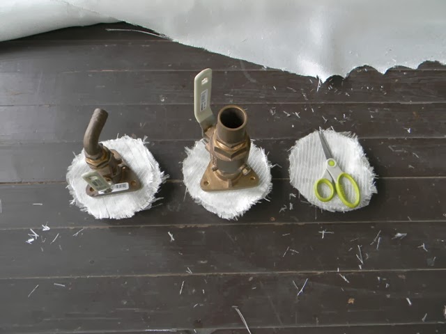
As I have done with so many other projects on this boat, I began by making a mock-up.
I knew that the new backing plate had to be ring-shaped. This would be the only way that I could deal with the bulge in the hull.
The idea was that the ring would encircle the bulge.
My plan was to fill the interior of the ring with multiple layers of fiberglass cloth. In this way, I could eliminate the bulge by covering it up and making the top of the backing plate one solid surface.
I was pleased to see that the mock-up backing plate fit well into the newly fashioned cutout in the hull liner. Likewise, I was pleased to see that the inner part of the ring was large enough to encircle the bulge and allow the entire ring itself to sit flush against the hull.
Given that the galley sink drain through-hull was 3/4 inch, just like the raw water intake through-hull in the head, I would be able to use the same sized ring-shaped backing plate in both areas. The mock-up fit just as well here as it did in the head.
Having figured out how to handle the backing plates for the two smaller through-hulls, I turned my attention to the construction of a mock-up for the large, waste outlet through-hull. I used the same sized hole saw that I had used for the other mock-up - a 5 inch one.
I decided, though, to try a different approach to cutting the ring. I began by making a disc with the 5 inch hole saw. Then, I clamped this plywood disc to the table and drilled the smaller hole through it. This was a much easier approach than the one I made the first time. I'm taking the time to mention all of this now, because this was the approach that I would take when I cut the real backing plates a short time later.
I should also note that this ring was the exact same size as the first one that I cut. Why, you might ask, would I not just use the same mock-up for all three holes?
Well, it all had to do with the special problem I faced with the installation of the 1.25 inch hardware in the waste outlet hole.
You'll remember I said that this waste outlet through-hull was angled with regard to its orientation in the area around the head. In other words, it did not project straight into the space within the head. Instead, it pointed toward the bulkhead. This was a problem, but there was also the problem that the original hole was situated very close to the fiberglass cleat into which the bulkhead was inserted. Do you see the large piece of fiberglass that is adjacent to the bulkhead? That's the cleat. I could not cut into this cleat to enlarge the area around the original cutout in the hull liner. Therefore, I had to modify the ring-shaped backing plate so that it would conform to the cleat.
I used the plywood mock-up as a pattern, around which I scribed a line with a red Sharpie marker. It should be clear by now that for this hole it would be impossible for me to use a hole saw to remove the unwanted portion of the hull liner.
No, for this job I would need to use the Dremel, with a special fiberglass cutting bit. I had used the bit on other projects on this boat, and I knew that it was especially easy to screw-up a work area with this tool and this bit if I was not very careful. Therefore, I decided the most prudent course of action would be to make a practice cut with this bit in a scrap piece of fiberglass.
It was imperative not only that I cut a smooth, circular line, but also that I not allow the bit to cut too deeply. This thing can do a lot of damage in a short period of time. I considered using the plywood mock-up as a jig, but I thought I had better control of the tool doing this job free-handed.
As I made the practice cut, I stopped from time to time to see how it looked on the other side.
Satisfied with my strategy, I returned to the boat.
As I slowly made the cut, I used a screwdriver as a lever to keep the liner as far as possible from the hull.
I was pretty pleased with the results. I'm not sure that I could have made this cut any cleaner. More importantly, since I took my time with this, there wasn't a single scratch on the hull.
After I had removed all of the old adhesive with a small chisel, I grabbed my Rockwell oscillating tool, and, with a sanding head attached, I cleaned up the area in and around the hole.
I was especially pleased to discover that the plywood mock-up fit nicely into this new cutout. Moreover, the ring sat flush against the hull, allowing the bulge to project into the inner area of the ring.
Satisfied with the mock-ups, I moved forward with the construction of the real backing plates. For these, I used 3/4 inch sapele (mahogany). If your curious to know why I use sapele for various projects, and why I simply call it
mahogany, see my series of articles, "Companionway Hatch Construction." I did consider using G-10 in lieu of mahogany. G-10 is fiberglass board that is constructed of multiple layers of epoxy-saturated fiberglass cloth. G-10 is an excellent material for backing plates, but it is notoriously difficult to cut. I was concerned that my Makita drill, despite its excellent torque, would die if I tried to cut through the G-10 with the large hole saws that I planned to employ.
I'm certain that I made the right decision in terms of opting for the mahogany over the G-10. Why? Because I came close to burning up my drill just by cutting through the mahogany. Despite my efforts to hold the drill perfectly still, the hole saw would nevertheless bind and bog down every few seconds during the lengthy drilling process. The drill became quite warm, and eventually it began to omit that telltale odor of a tool that is overloaded.

This Makita drill is no cheapie. It's one tough drill. I've used it to drill all sorts of things. Here's a good story. I bought a mid-range DeWalt drill from a local home improvement store to assist me in my construction of a fence. After I got back home, I put an augur bit into the DeWalt and tried to drill through a pressure-treated 4 x 4 fence post. The DeWalt burned up before I could make it all the way through the post. I promptly returned the DeWalt and spent the extra dollars to get the Makita. This Makita had no problem pushing the augur all the way through the 4 x 4. Several days later, I was working on another fence post, this one a 6 x 6. I loaded up the Makita with the very same augur bit and placed the tip of the bit on the appropriate spot on the post. When I pulled the trigger, I mistakenly hit the trigger lock at the same time. Due to the sudden torque from the augur hitting the dense wood, the drill spun out of my hands . . . but it did not fall to the ground. Instead, it drilled itself all the way through that post. I could tell other stories, but the point is that this Makita is a real workhorse, but despite its toughness, the large hole saws that I used to cut these mahogany backing plates almost killed it.

I do everything I can to minimize the waste when cutting mahogany. It's just too expensive to let any of it go to waste. I'm still not sure how I was able to pull this one off, but somehow I was able to get two backing plates out of this one small scrap.
Having cut the backing plates for the raw water intake and the galley sink drain, it was now time to focus on the backing plate for the waste outlet through-hull.
As always when working with mahogany, I used 40 grit paper to sand out any imperfections. As I've said in other postings, 60 grit paper will do the job, but it takes much longer. Even with 40 grit, you're going to spend some time on it. Yes, it's really that hard. I use the same grit when sanding epoxy.
What I couldn't do with the quarter-sheet sander, I did by hand. This also is 40 grit paper.
My next move was to epoxy-coat the mahogany.
After several hours I came back and applied a second coat.
The next day, I turned the pieces of mahogany over and epoxy-coated the second side.
Just as was the case with the first side, this side got a second coat. The imperfections you see on the surface of the wood are dried pieces of epoxy. These resulted from the pooling of the epoxy on the plastic on the previous day.
After about two days, I set up this temporary sanding table in the yard and began to hit the mahogany with 40 grit paper in the quarter-sheet sander.
I used the Dremel with a 50 grit sanding wheel to do the inner part of each ring.
Having prepared the mahogany backing plates, it was now time for me to cut the cloth. I used two different types of fiberglass cloth - regular, 10 ounce cloth; and 12 ounce biaxial.
I used the regular 10 ounce cloth for the center of the ring. Each ring received 20 layers of 10 ounce cloth. Yes, that right . . . 20 layers.
I used the 12 ounce biaxial cloth for the top of the backing plates. Each backing plate received two layers. I figured these layers of cloth would serve a dual purpose: they would seal everything up, and they would bond with the 20 layers of cloth in the center.
Ready to roll.
But . . . before I could install the backing plates, I had to make sure that the hull (in the area around the through-hulls) was as clean as possible. For this, I turned to toluene.
The space beneath the galley sink was filthy, with over 35 years of worth of dust and dirt.
The toluene soaked rag says it all.
Even after a thorough rubbing with the toluene, this area still had its share of imperfections.
Adhesive and/or sealant from the old backing plate still clung to the hull. The chisel helped with this job.
Afterwards, I pulled out a different weapon - xylene - a solvent known for its wax and adhesive cutting properties. I figured this would help remove any remaining residue from the old adhesive.
I was right.
Now that this area was as clean as it possibly could be, it was time for me to do some sanding.
For this, I used my Rockwell oscillating tool with the triangular sanding head attachment.
The 50 grit paper did an adequate job roughing up the surface of the fiberglass.
To roughen the surface up even more, I used a wire brush.
After hitting the area with the Shop-Vac, I pulled out the xylene once again.
This effort was not in vain. Residue still remained.
The galley sink drain through-hull area in its fully-prepped state.
For this job, as with so many other jobs, I used RAKA epoxy and colloidal silica.
I began by wetting out the work area with neat epoxy. Then, after I had fully soaked the hull and the ring, I thickened the epoxy to the consistency of peanut butter with the colloidal silica. I spread the thickened epoxy over the hull and allowed it to sit for a short time until it started to kick. I wanted it to be good and sticky before I applied the ring. This way the ring would stay in place after I pushed it down into the bed of epoxy. This technique worked. Once I put it there, it didn't move.
I then allowed the ring to sit for several hours. I didn't want to load up the center of the ring with the 20 layers of cloth and epoxy until the ring was firmly clinging to the hull.
When the time came to apply the 20 layers of cloth I thought it wise to apply these layers in two separate lay-ups of 10 layers each. I was concerned that if I applied too many at one time I would cause the epoxy to overheat. When I had finished the first lay-up of 10 layers, I thickened up the remaining epoxy and spread it around the outside of the ring to create a fillet. This fillet would not only help to support the ring, but also it would help to prevent water from running underneath the mahogany (from condensation on the hull)
An hour or two after I had completed the first lay-up, I came back and applied the final 10 layers of cloth.
After that, I finished the job by applying the two layers of 12 ounce biaxial cloth. Having fully wet-out the cloth, I thickened the epoxy with colloidal silica and filled the weave to create a smooth surface.
A couple of days later, after the epoxy had cured, I came back with the power tools to clean up the work area. I started by sanding away the rough edges with the Dremel.
The Dremel did a fantastic job. I can't imagine trying to do this job (or many others on this boat) without this tool and its accompanying right-angle attachment.
The Rockwell oscillating tool was also very helpful for cleaning up the edges.
To finish the job, I applied the quarter-sheet sander with 40 grit paper.
This made the surface of the backing plate both smooth and level.
Before I called this part of the project complete, I did a little hand sanding with 40 grit paper around the fillet.
Curious to see how well the Groco flange might fit on this new backing plate, I grabbed it and set it in place.
I thought the whole thing looked pretty good.
Now it was time to move to the two through-hulls in the head. This was a tough work area. Of course it was cramped, but the worst thing about it was that I had to kneel on the sole and position my shins across the threshold of the door. I used a towel as a pad of sorts, but it didn't offer much relief. The hose you see in the picture is one of several that I cut and routed throughout the head prior to doing this job. I had to make sure that the hoses would not interfere with the handles of the inline valves that I planned to install atop the flanges.
I started by wiping both holes with xylene.
The waste outlet through-hull area had quite a bit of adhesive on it that I had to remove. Xylene helped. So did the chisel.
Same story for the raw water intake hole.
Both holes after they were thoroughly cleaned.
Waste outlet.
Raw water inlet.
Before doing anything else, I decided it would be a good idea to protect the hull liner with duct tape.
Just as I had done on the galley sink hole, I used a steel cup brush to roughen-up the areas around these holes.
I also used the Dremel for the hard-to-reach places.
Likewise, I used the pointed edge of the Rockwell oscillating tool to roughen-up the area around the edge of the hull liner.
One last wipe with xylene, and I was ready to do some epoxy work.
In preparation for the epoxy work, I spread out some plastic and secured it with duct tape. I also placed a small piece of OSB in this space to serve as a work table of sorts.
I glued the rings to the hull with epoxy in the same fashion as the ring under the galley sink.
I started by laying-up 10 layers of 10 ounce cloth in each hole.
After I finished this lay-up, I climbed out of the boat to see how the holes looked on the exterior of the hull. Not surprisingly, these holes, just like the galley sink drain hole, were oozing epoxy.
After addressing the ooze issues on the exterior of the hull, I returned to the interior to lay-up the next 10 layers of 10 ounce cloth in each hole.
I then applied the first layer of 12 ounce biaxial cloth.
And then the second layer.
And then additional coats of thickened epoxy to fill the weave.
You might have noticed that with these two holes in the head, I laid-up all the cloth at the same time. There was a reason for this. Given that I had never felt any excessive heat build-up during the lay-up of the 20 layers of 10 ounce cloth and the 2 layers of 12 ounce biaxial cloth in the area under the galley sink, I decided that with these two holes in the head I would lay-up all of the pieces of cloth at one time. In other words, I would not apply the cloth 10 layers at a time.
You're probably wondering if this worked. Yes, it did. This accelerated lay-up in the head did not cause any problems whatsoever. I never felt any excessive heat. Yes, the hull was warm, but it was not hot, and I should point out that the air temperature on this day was around 90 degrees Fahrenheit. The temperature in this enclosed space within the boat? It had to have been around one hundred. I believe the reason why there was not excessive heat was that, although this cloth was soaked with epoxy, it was not deep with it. In other words, there was far more cloth than there was epoxy.
Several days later I came back and sanded the backing plates in the same fashion that I had sanded the one under the galley sink.
I used the fiberglass cutting bit on the Dremel to clean up the narrow slot between the backing plate and the bulkhead cleat.
The finished product for the large hole.
The finished product for the small one.
The construction and installation of these new backing plates took a considerable amount of time. Nevertheless, this lengthy sub-project of the overall through-hull replacement project, was one that brought some measure of satisfaction. I had approached this job with forethought and patience, and the end products were both functional and pleasing to the eye. Now, with a little more patience, I could move forward with the next sub-project: the drilling of the new holes through these new backing plates.
This ends Part 5 of this multi-part article on how I installed new bronze through-hulls in
Oystercatcher, my Ericson 25.


No comments:
Post a Comment